PIC16F84A Microcontroller
available at 1 shops · updated 2h ago
Description
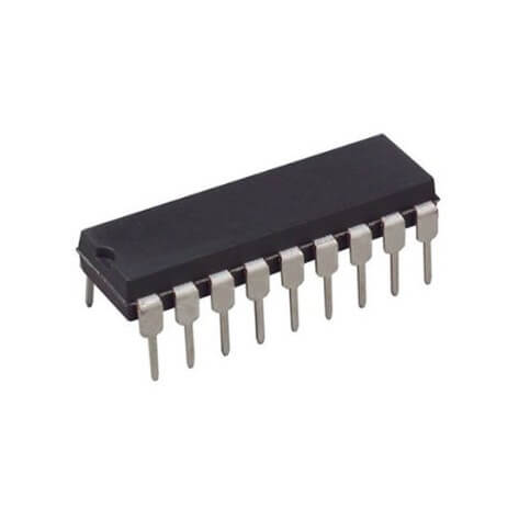
buy Microcontrollers Devices In Egypt PIN Diagram of PIC16F84A This is an 18 pin IC, the description of each pin are given below: ? It has thirtheen GPIO pins and each pin can be used either as digital input or digital output. These 13 GPIO pins are shared with PORTA and PORTB. PORTA consists of 5 pins from RA0-RA4 and PORTB has 8 pins from RB0-RB7. Explanation of GPIO pins? Pins 1,2,3,6,7,8,9,10,11,12,13,17&18: These 13 GPIO pins can be independently configured either as digital input or as digital output. Also, each pin can either supply or can absorb a maximum of 25mA current per pin. So, accordingly, every pin can drive a?LED?easily but cannot drive any dc motor or relays. Because, current requirement for LED is generally less than 10mA and dc motor requires greater than 25mA.? ?If you want to interface relay or dc motor, you have to use current driver ICs. Like??motor driver IC?to interface motor and?relay driver IC?to interface single of multiple relays.? The mentioned 13 I/O pins are assembled into two groups known as ports. Port A:?contains 5 pins which are 1, 2, 3, 17 & 18 on pinout or RA0, RA1,RA2,RA3,RA4. Port B:?contains 8 pins which are 6, 7, 8, 9, 10, 11, 12 & 13 or RB0, RB1, RB2, RB3, RB4, RB5, RB6, RB7. Pin 4:?This is an active low pin known as MCLR (Memory Clear). Obviously, this pin is used to reset the device . Whenever it is kept low while connecting to the ground then it reset the device. Circuit below shows the reset circuit in blue color highlighted reg
Available at
| Shop | Price | Stock | ||
|---|---|---|---|---|
| MOMicro Ohm | 150 | in stock | buy |